Home > Foundation > Linear Motion vs. Angular Motion
Linear Motion vs. Angular Motion
Any complex motion of a body can be broken down to two simple motions: linear motion and angular motion. Linear motion is translation from one position to another while angular motion is rotation about an axis or center of rotation. Linear motion can also be viewed as motion of a point and have two types: rectilinear (straight path) and curvilinear (curved path).
Figure 1 shows the motion of a club (driver) during downswing observed in the functional swing plane. The mid-hand point, mid-point of the hand centers, moves along a curved path (curvilinear motion) with varying curvature while the club also rotates about the mid-hand point.
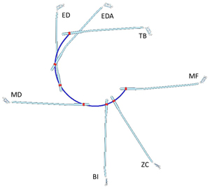
Figure 1. Motion of the club during the downswing. The red dots are the positions of the mid-hand point at various downswing events and the blue line is the trajectory of the mid-hand.
This club motion can then be broken down to two simple motions: linear motion of the mid-hand point (Figure 2A) and angular motion of the club about the mid-hand (Figure 2B). In this case, the mid-hand point was selected as the representative point of the club as the focus is how the hands guide the club and how the club rotates around the hands. This is actually a common practice in biomechanics to break down a complex motion to linear motion of a point on the object and angular motion of the object about the point. It is easier to handle these simple motions separately than the actual complex motion at once. Actually, since linear motion and angular motion are very different in nature, these must be separated for an in-depth analysis.
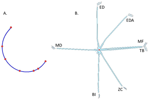
Figure 2. Simple motions of the club during the downswing: linear motion of the mid-hand point (A) and angular motion of the club about the mid-hand point (B).
Selection of the representative point depends on the interest of the investigator. In the example above, the mid-hand point was used as the point of interest and the club motion was broken down to linear motion of the mid-hand point and angular motion of the club about the mid-hand point. If you are interested in the stand-alone motion of the club (without considering the hand-club interaction), club's center of mass (COM) may be used as the point of interest (Figure 3). This COM perspective is commonly used in Newtonian mechanics.
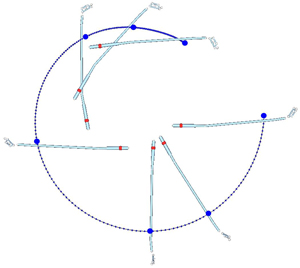
Figure 3. Motion of the club during the downswing in the COM perspective. The blue dots are the positions of club's COM at various downswing events and the blue line is the trajectory of the COM.
It is important here to understand that the point of interest used in breaking down the club motion doesn't have to be a fixed physical center of rotation. This is the source of a common misconception but the point of interest is just used to break down a complex motion to simple but meaningful linear and angular motion elements.
Another example of a complex motion commonly broken down to meaningful linear and angular motion elements is the pelvis motion (Figure 4). In this case, the complex pelvis motion can be broken down to linear motion of the pelvis COM (forward/backward, toward/away, and upward/downward motions; Figure 4A) and angular motion of the pelvis about its COM (left/right rotation, right/left tilt, and posterior/anterior tilt; Figure 4B) with the pelvis COM being the point of interest. These six motions (3 linear + 3 angular) are all independent from each other and collectively refered as 6 degrees of freedom (DOF).
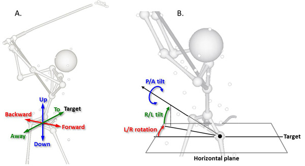
Figure 4. Breaking down of the pelvis motion tolinear motion of the pelvis COM (A) and angular motion of the pelvis about its COM (B). Pelvis COM was used as the point of interest in this case. The orientation angles of the pelvis are in the 'rotation -› lateral tilt -› tilt' sequence. Abbreviations: R/L (right/left), P/A (posterior/anterior).
Note in Figure 4B that the orientation angles of the pelvis is computed in the order of 1) rotation, 2) lateral tilt, and 3) tilt. As a result, the 'rotaton' angle is measured on the horizontal plane while the 'lateral tilt' angle is measured on the vertical plane that contains the hip line that connects both hips. The 'tilt' angle is measured on the plane perpendicular to the hip line. The angle convention may differ among different vendors and platforms so caution must be used in cross-platform comparison of the orientation angle data. The main strength of this 'rotation -› lateral tilt -› tilt' sequence is its intuitiveness as one can intuitively connect a given set of orientation angles to matching pelvis orientation. The rotation and lateral tilt angles can easily be figured from the direction of the hip line.
Figure 5 shows the changes in pelvis position (A) and orientation (B) during driving of an elite male player. The initial positions of the pelvis COM and orientations of the pelvis were used as zeros. By breaking the pelvis motion to linear motion of the pelvis COM and angular motion of the pelvis about its COM, one can characterize and scrutinize the golfer's pelvis motion and identify issues.
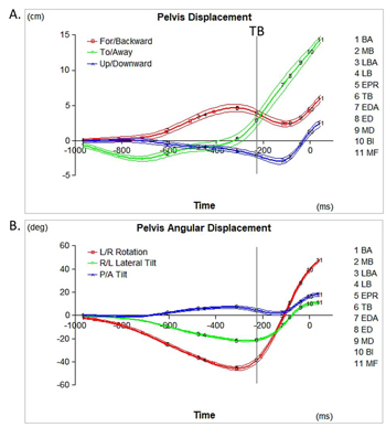
Figure 5. Changes in pelvis position (A) and orientation (B) from the initial position and orientation, respectively, during the swing of a PGA Tour-caliber player (drive). The graphs show the means and standard deviations of five trials. Time is in ms relative to BI.
Related Readings