Home > Foundation > Moment of Force
Moment of Force (Torque)
Moment of force (torque) or simply moment is the cause of angular motion (rotation). Moment of force is caused by a force which does not pass through the center of rotation (COR). Figure 1 shows a wrench system which is used to rotate a circular object (let's call it a nut). Since the task here is to rotate the circular nut, the COR is located at the center of the nut. The force (F) that is applied by the hand to rotate the nut and wrench is acting on the point of action (POA) on the handle along the line of action (LOA; dotted line). In this example, the plane of action is the monitor screen which is perpendicular to the line of sight. If the force is sufficiently large, the wrench and the nut will rotate in the clockwise direction on the plane of action or plane of rotation.
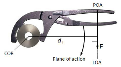
Figure 1. The moment arm formed by the hand force acting on a wrench
What actually causes the rotation of the nut in Figure 1 is the moment generated by the hand force. The magnitude of the moment generated by the hand force depends on two parameters: force magnitude and length of the moment arm. Moment arm ( in Figure 1) is the shortest (i.e. perpendicular) distance from the COR to the LOA. Moment arm is defined on the plane of action/rotation. The moment generated by the hand force (F) in Figure 1 is thus:

Where M = magnitude of the moment. Moment is proportional to the force applied and the moment arm formed by the force with respect to the COR (Equation 1).
Moment is a vector so it should have its direction. The direction of the moment generated by a force is always perpendicular to the plane of action. Plane of action is the plane formed by the moment arm and the force vector. The right-hand screw rule is used in determining the direction of moment; when four fingers of the right hand are aligned along the direction of rotation, the thumb shows the direction of the moment (Figure 2). A right-hand screw moves forward when it is rotated clockwise.
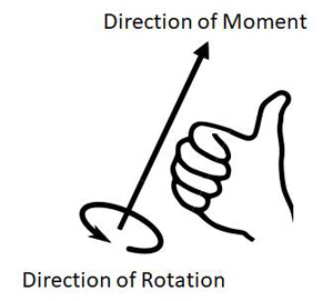
Figure 2. Direction of rotation vs. direction of the moment causing the rotation (image source: http://www. wikipedia.com)
Unlike a simple planar motion in which the plane of action is perpendicular to the line of sight (Figure 1), identification of the moment arm and the direction of the resulting moment acting on a freely rotating body in the 3-dimensional space is more complex. For example, Figure 3 shows the GRF (F) acting on the lead foot and the moment (M) generated by this force about the COM of the body. Since the body rotation is not constrained and there is no fixed COR in this case, the COM of the body can serve as the COR in the perspective of the angular effect of the lead foot GRF on the body.
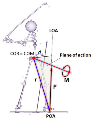
Figure 3. Moment of force generated by the lead foot GRF about the body COM near EDA
Note here that the lead foot GRF is not necessarily on the frontal plane: i.e., its froward/backward component is not zero. The easiest way to visualize the plane of action in the 3-dimensional space is to draw an arrow (r) from the COM (COR) to the POA. This is the relative position vector of the POA to the COR. The plane defined by r and F is the plane of action. The moment arm can be identified on the plane of action. The moment arm forms a right angle to the line of action of the GRF (Figure 3).
Mathematically, the moment (M) can be expressed as the vector product of the position vector (r) and the force vector (F):

The vector product is a special way to multiply two vectors. Because of the cross symbol ('x') used, this mathematical operation is also called cross product. When the relative position and force are given in components, the moment can also be expressed in components:

The resulting moment vector (M) given in components in Equation 3 suffices two requirements: (1) its magnitude is equal to the length of the moment arm times force magnitude; (2) its direction is perpendicular to the plane of action in accordance to the right-hand screw rule. The moment vector also has three perpendicular components:

Figure 4 shows three postures of an elite male golfer observed in three different views: frontal (A) near EDA, side (B) near BI, and horizontal (C) near EDA. The X-, Y-, and Z-axis of the reference frame are aligned along the forward/backward (F/B), toward/away (T/A), and upward/downward (U/D; vertical) axes, respectively. In Figure 4A,  is the projection of the lead foot GRF on the YZ-plane which is perpendicular to the F/B axis (X-axis).
  is the moment arm formed by this force with reapect to the COM on the YZ-plane. In Figure 4B, the GRF vector was projected onto the XZ-plane (
 ) and from this force, the moment arm (
 ) was identified on the same plane. Similarly, both
  and
and  in Figure 4C are defined on the horizontal plane. The magnitudes of the moment components are thus:

The signs (+/-) of the components should be determined based on the directions of the moment components. If a moment component is in the counterclockwise direction (Figures 4A and 4C), the sign should be positive. A clockwise moment (Figure 4B) is negative.
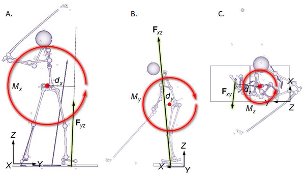
Figure 4. Components of the moment observed in three views: frontal view (A), side view (B), and horizontal view (C).
Each moment component can be further broken down to two separate terms generated by the individual force components. For example, Figure 5 (frontal view) shows the moments generated by  and
and  . In this case, the Y- and Z-components of the relative position vector of the POA to COR (y and z) serve as the moment arms of the force components. Both force components in Figure 5 generate moments in the counterclockwise direction (positive). Since the Y-component of r (y) and the Z-component of F both are positive, so y * Fz should also be positive. The Z-component of r however is negative, while the Y-component of F is positive. Since z * Fy becomes negative, a negative sign should be added to make the direction positive.
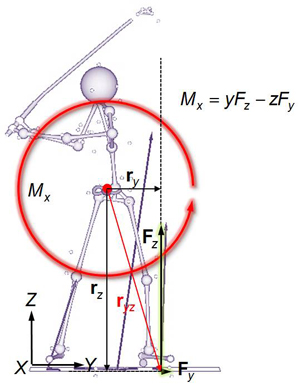
Figure 5. Resolution of the F/B-axis moment (Mx) into two terms generated by individual force components.
One important aspect of the moment produced by the lead-foot GRF about the F/B axis (Figure 5) is that this moment is sensitive to the horizontal force acting along the T/A direction ( ). This is why the horizontal interaction between the golfer and the ground in the frontal plane is so important.
See the Golfer-Ground Interaction Moments page for the moments generated through the golfer-ground interaction during the swing.
Top