Home > Foundation > Scalar vs. Vector
Scalar vs. Vector
Scalar and Vector Quantities
Mechanical quantities are largely classified into two groups: scalars and vectors. A scalar quantity (such as mass, speed, power, work, energy, etc.) holds magnitude only while a vector quantity (such as position, velocity, acceleration, force, moment of force, linear and angular momentums, etc.) has both magnitude and direction. Most of the mechanical quantities associated with motion of an object are vectors. In the equations, scalars typically use italic symbols (such as m) while vectors use bold symbols (such as F).
Treating scalars is easy as they only have magnitude. One can directly add two scalars of the same kind. For example, if the mass of object 1 is 100 kg and that of object 2 is 80 kg, the combined mass is 180 kg (100 + 80). Treating vectors, however, is more complex as vectors involved may not necessarily have the same directions. When directions are different, magnitudes cannot be simply added. For example, if the magnitude of the first force acting on an object is 100 N and that of the second force acting on the same object is 80 N, the combined (net) force is not necessarily 180 N but depends on the relative directions of the forces to each other. There is a specific way to treat vectors.
The easiest way to visualize a vector is using an arrow. The length of the arrow means its magnitude while the tip shows its direction (Figure 1A). The length of the arrow should be proportional to the magnitude when multiple arrows are used (Figure 1B).

Figure 1. Vector arrow
Top
Vector Addition: The Tip-to-Tail Method
One commonly performed task indealing with vectors is addition. The vector addition procedure can be expalined by the procedure called 'tip-to-tail method' (Figure 2). Let's assume there are three force vectors acting on an object at the same time (Figure 2A). Here are the steps of adding the vectors using the tip-to-tail method:
- Connect all vectors tip to tail. The tail of the second vector should be placed at the tip of the first vector and so forth. In this process, vectors can be moved freely as long as the magnitudes and directions are unaltered (Figure 2B).
- Draw an arrow from the tail of the first vector to the tip of the last vector (red arrow in Figure 2C). This is the resultant (sum) vector.
- The order of addition is not important as vector addition is commutative and will result in the same outcome (Figure 2D).
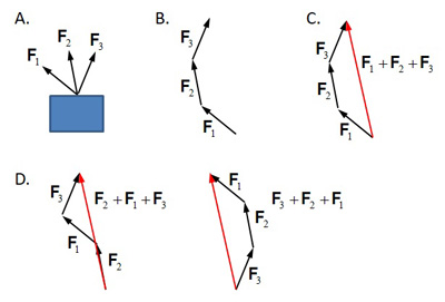
Figure 2. The tip-to-tail method of vector addition
The tip-to-tail procedure can be applied to any number of vectors. Individual vectors may be replaced with the resultant vector as they are mechanically equivalent. FIgure 3 shows a realistic example of vector addition: computation of the combined ground reaction force (GRF) from two individual ground reaction forces (lead foot and trail foot). GRFs are the reactions to the forces exerted to the ground by the feet. See the Ground Reaction Force and Moment page for details. The combined GRF is the vector sum of individual GRFs. While in Figure 3 the vector additions were performed plane by plane in the frontal plane (Figure 3A) and in the horizontal plane (Figure 3B), it can also be done in 3-dimensional space. In both planes, the lead foot and trail foot GRFs were connected tip to tail and the combined GRF was drawn from the tail of the trail foot force to the tip of the lead foot force.
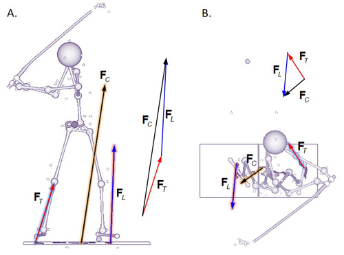
Figure 3. Individual ground reaction force vectors and the combined ground reaction force vector computed through vector addition. The three vectors suffice the tip-to-tail procedure requirements.
Top
Vector Negation and Subtraction
FIgure 4 shows additional basic vector operations commonly used. When a positive scalar is multiplied to a vector, the direction of the vector remains the same while the magnitude changes (Figure 4A). If the scalar value is larger than 1, the vector magnifies. If the value is smaller than 1, the vector shrinks. If -1 is multiplied, the direction reverses (vector negation; Figure 4B). Vector subtraction is essentially an extenion of vector addition with one vector negated (Figure 4C).
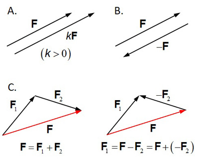
Figure 4. Additional basic vector operations: multiplicaton by a scalar (A), negation (B), and subtraction (C)
Top
Vector Decomposition and Components
One observation that can be made from vector addition is that if multiple vectors can be added to yield the resultant vector, it is also possible to break down a vector into multiple vectors as long as the sum of these vectors remains the same. A common way to do it is to break down a vector into multiple 'component' vectors perpendicular to each other. For example, Figure 5 shows the position of the pelvis center of mass (CM) at event TB. The position vector is essentially the arrow drawn from the origin of the coordinate system to the location where the pelvis CM is at a given time point. Here are some key observations:
- For objective (not subjective) description of the position of a point at a given time point, a 'coordinate system' or 'reference frame' must be defined, such as the OXYZ system shown in Figure 5A. The origin is located at the right rear corner of the trail foot force plate. The directions of the +X axis, +Y and +Z axes are forward, toward the target, and upward, respectively. This type of coordinate system is called 'Cartesian' or 'rectangular' coordinate system in which all axes are perpendicular to each other.
- The position vector (r) can decomposed to three component vectors parallel to the coordinate axes. The component vectors are all connected in the tip-to-tail fashion so the sum of these three component vectors must be equal to the position vector (Figure 5A). The component vectors are perpendicular to each other and thus are independent from each other.
- The three component vectors may be replaced with three scalar coordinates (x, y, and z) which can be either positive or negative depending on their directions on the respective axes (Figure 5A).
- The coordiantes can be plotted over time (Figure 5B) to show the motion of the pelvis CM in three directions: forward/backward (X), toward/away from the target (Y), and upward/downward (Z).
- The coordinates of the pelvis CM can also be described relative to its initial position in the setup position (Figure 5C). This plot clearly shows how the pelvis CM moves away from its inital position as the swing progresses. This plot is useful in assessing the pelvis motion pattern of the golfer. The pelvis CM moves forward until event EPR and then starts moving backward to the EDA position (red line). It moves forward again thereafter. It also moves away from the target initially but start moving toward before the golfer reached the MB position (green line). Around the EPR position it passes the initial position and stays more toward the target thereafter. The pelvis CM moves downward during the entire backswing and the direction reverses near the EDA position (blue line).
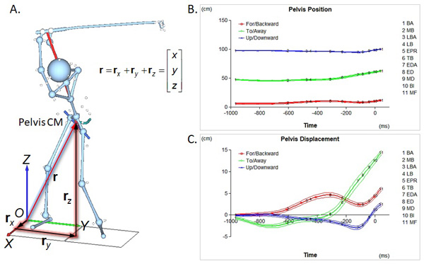
Figure 5. Motion of the pelvis center of mass (CM): component vectors of the position vector (A), coordinates of the pelvis CM over time (B), and relative position of the pelvis CM to its initial position
Vector decomposition and description of the vector using the components can be applied to any vector, not just the position vector. For example, Figure 6 shows the net mid-hand (MH) forces acting on the grip at various downswing positions and the moving MH reference frame axes in the functional swing plane (FSP) view:
- The MH point is the center of the hands which is considered a virtual joint between the hands and the club in the assessment of the hand-club interaction. The MH force (black arrows in Figure 6A) is the sum of all grip forces acting on the grip by the hands. The magnitude and direction of the net MH force keep changing throughout the swing.
- The moving MH reference frame is a Cartesian coordinate system with three perpendicular axes: swing (S), tangential (T), and normal (N) (Figure 6A). The swing axis (appearing as red dots placed at the origins) is perpendicular to the FSP while both the tangential (green arrows) and normal (blue arrows) axes are defined on the FSP. The tangential axis is tangential to the projected trajectory of the MH point (dark green line) on the FSP while the normal axis is perpendicular to the tangential axis on the FSP. The MH reference frame moves with the MH point.
- The net MH force can be decomposed based on the moving MH reference frame axes (Figure 6B). The swing axis component (red line) shows the force acting on the grip in the direction perpendicular to the FSP (the off-plane component). Both the tangential (green line) and normal (blue line) components show the on-plane force components. The swing axis component of the net MH force is minimal throughout the entire downswing.
- The tangential component increases until event MD where the club becomes parallel to the ground and then starts decreasing (Figure 6B). It stays positive in the downswing meaning dragging the grip all the time in the direction of hand motion. The normal component is negative (outward to the hand path) initially until about 50 ms before the impact and then turns to and stays positive (inward) thereafter. It becomes maximum at BI.
- The reference frame used in decomposition of a vector does not have to be fixed or parallel to the global coordinate axes. A vector can be decomposed to any combinations of component vectors as long as the axes carry practical meanings. Note here that the directions of the tangential and normal axes keep changing throughout the swing. Therefore the tangential components derived from two different positions are not in the same direction. Note also that it is possible to define the moving MH reference frame in slightly different ways, depending on the analysis intention.
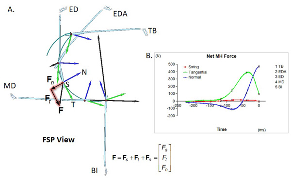
Figure 6. Decomposition of the net mid-hand force in the moving mid-hand reference frame: axes and force vectors at various downswing positions (A) and force component-time plot (B)
Top
Unit Vector
The magnitude of a vector can be computed from the components. For example, the magnitude of the net MH force shown in Figure 6A can be computed from its swing, tangential, and normal components:

Equation 1 is commonly known as the Pythagorean Theorem. A vector whose magnitude is equal to 1 is called 'unit vector:'

The unit vector of a given vector can be computed by dividing the vector by its magnitude:

where f is the unit vector of F. A vector can be expressed as the product of its magnitude and unit vector:

The component vectors can also be expressed as the product of its unit vector and magnitude. For example, the net MH force vector can be expressed as:

where s, t, and n are unit vectors of the swing, tangential, and normal axes, respectively.
Top
Vector Addition and Subtraction: The Component Method
When the components are known, vector addition and subtraction can be done based on the components:

In other words, addition or subtraction can be done component by component. This operation yields exactly the same result to the tip-to-tail method explained above. Note here that the components of the vectors to be added or subtracted must be described in the same reference frame. Only the components based on the same axis can be added or subtracted. The tip-to-tail method is used in visualizing the resultant vector while the component method is used in actual computation of the components of teh resultant vector.
Top