Home > Foundation > Angular Position
Angular Position
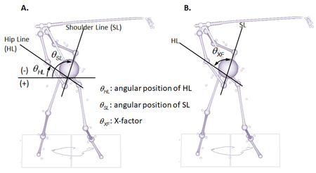
Angular position is defined as the 'angular location' of an object at a given time point. In the 2-dimensional perspective, angular location is described by the angle measured on the plane of interest from the reference line. For example, Figure 1A shows two angles defined on the FSP (functional swing plane): the hip line (HL) angle formed by the line connecting the hip joint centers and the shoulder line (SL) angle formed by the line connecting the shoulder joint centers. Both angles are measured from the horizontal line. The horizontal line is used as the reference line in this case because that way these angles become close to zero in the setup position. The direction can be described as either counterclockwise or clockwise. It is a common convention that the angle measured in the counterclockwise direction holds a positive value, vice versa. Therefore, the HL and SL angles stay negative during most part of the backswing (Figure 1A) and early part of the downswing until the lines return to horizontal alignment. The HL and SL angles are useful in describing the on-plane angular motion of the respective lines.

Figure 1. Two angles defined on the FSP, hip line angle and shoulder line angle (A), and the X-factor (B). The HL and SL angles are measured from the horizontal line (leftward) while the X-factor is the angular distance between these lines.
Angular distance, on the other hand, only concerns the magnitude of the angle formed by two lines. A good example of this is the X-factor shown in Figure 1B. The X-factor is the angle formed by the HL and SL. In the original version, the X-factor was measured on the horizontal plane but the FSP-based X-factor is used here instead since the FSP is considered as the main plane of motion. As the angular separation between HL and SL increases, the X-factor increases regardless of the direction.
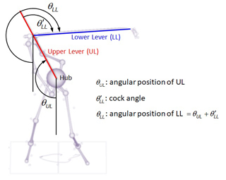
Additional examples of angular positions defined on the FSP are presened in Figure 2. The angular positions of the upper lever (UL) and lower lever (LL) are measured from the vertical line (going downward) so the values become close to zero in the setup position. The reference line can be selected in accordance to your analysis intention. See the Functional Double-Pendulum page for detailed definitions of the levers used in the functional double-pendulum (FDP) model.

Figure 2. The upper lever (UL) and lower lever (LL) angles defined on the FSP. The UL and LL angles are measured from the vertical line (downward) while the wrist cock angle is the relative position of the LL to the UL.
Among the angles shown in Figure 2, the wrist cock angle is an example of relative angular position of one moving line (LL) to another (UL). This relative angular position describes the joint motion at the mid-hand point, the virtual joint that connects the hands to the club. Angular position of the LL is therefore the sum of the angular position of UL and the wrist cock angle. Or, the wrist cock angle is angular position of the LL minus that of the UL.
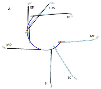
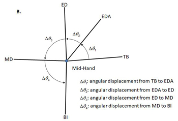
Angular displacement is the amount of angular motion (rotaton) of the line of interest from one time point to another or the angle measured from the position at time point 1 to that at time point 2 (Figure 3). Figure 3A shows the actual motion of the club at various downswing events. In Figure 3B, however, the linear motion was eliminated and the shaft lines were put together at the mid-hand point. Angular displacement is the amount of rotation from one time point to another. The angular displacements of the shaft from ED to MD and MD to BI are close to 90° as these events were identified based on the club position in the frontal view. It is important to keep the angular displacement from TB to EDA small for a delayed release of the wrist and a high clubhead speed at impact.


Figure 3. On-plane motion of the club: actual (A) and angular displacements (B). In B, club's linear motions were ignored and angular displacements were measured in each downswing phase.
Description of the planar angular motion of a moving line is easy as it only requires identification of the plane of interest and the reference line. The orientation (attitude) of a given body segment (such as pelvis) in the 3-dimensional space is substantialy more complex as it requires computation of three orientation angles. See the Orientation Angles page for details.